Veins
This topic describes creating and editing veins. It is divided into:
- Creating Veins
- Veins in the Project Tree
- Displaying Veins
- Refining Veins
- Surfacing Options for Veins
- The Vein Reference Surface
- The Vein Boundary
- Editing Vein Segments
For a general introduction to how veins interact with other contact surfaces, see Vein Contact Surfaces in Contact Surfaces.
A vein is a type of contact surface that removes existing lithologies and replaces them with the vein lithology within the boundaries defined by hangingwall and footwall surfaces constructed from selected input data. A reference surface is defined that is the best fit for the hangingwall and footwall surfaces. The reference surface can be curved or planar.
Creating Veins
Options for creating veins are:
- From lithology data, using the base lithology used to define the geological model or other contacts available in the project. See Veins From Lithology Contacts below.
- From GIS vector data, point data and polylines. See Veins From Other Data below.
- Creating a vein system. This results in a single lithology that represents all the veins in a model. Veins and their interactions are defined within the vein system. See Vein Systems.
Veins From Lithology Contacts
To create a new vein from lithology contacts, right-click on the Surface Chronology object and select either New Vein > From Base Lithology or New Vein > From Other Contacts. The only difference in the two methods is that when creating a vein from other contacts, you must first select the lithology column from those available in the project and specify the Vein lithology and Outside lithology.
In the New Vein window, select the Vein lithology:
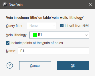
When extracting the hangingwall and footwall points, Leapfrog Geo automatically includes points at the ends of the drillholes. To exclude these points, untick the Include points at the ends of holes. Once the vein has been created, this setting can be changed by double-clicking on the vein segments object (![]() ) in the project tree.
) in the project tree.
Click OK to create the vein, which will be added to the project tree as part of the Surface Chronology object.
Veins From Other Data
If suitable lithology data is not available, veins can be created from other data in the project, such as GIS data, points and polylines. The steps for creating veins from other data are similar, regardless of the data used to create the surface:
- Right-click on the Surface Chronology and select one of the data types from the New Vein menu.
- Select the data objects for the Hangingwall and Footwall. These objects must already be in the project.
- Select the Vein lithology and the Outside lithology. The lithologies you can choose from are those defined for the geological model in the Lithologies object (see Model Lithologies).
Here, points data is being used to create a vein:
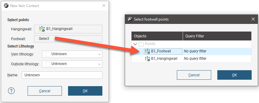
Select points data objects for both the Hangingwall and Footwall, then click OK to create the new vein. The new contact surface will appear in the project tree under the Surface Chronology. Expand the vein in the project tree to see how it was made.
Veins in the Project Tree
Veins are stored in the project tree as part of the Surface Chronology object. Further modifications can be made to the vein by working on the objects that make up the vein. Expand the vein in the project tree to view these objects.
Here, the hangingwall and footwall surfaces and points are displayed in the scene for a vein defined from lithology data. The reference surface (yellow) and the vein segments (red and blue cylinders) used to create the vein are also shown:
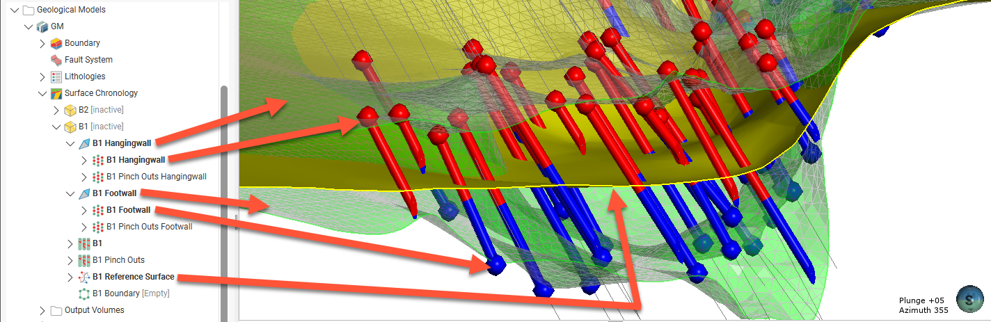
This vein is made up of:
- Hangingwall and footwall surfaces (
 ), which, when expanded, show the hangingwall and footwall data objects used to create the surfaces.
- Export hangingwall and footwall surfaces as described in Exporting Meshes and Exporting an Elevation Grid.
- Add points and GIS vector data to these surfaces () by right-clicking on them and selecting Add.
- Edit the hangingwall and footwall surfaces with polylines by right-clicking on them and selecting one of the Edit options.
- Change contact honouring and boundary filtering options as described in Surfacing Options for Veins below.
- Vein segments and pinch out segments (
 ) extracted from drillhole data.
 - These are only included when a vein is created from lithology contacts.
- If Vein Pinch Out
- A reference surface (
 ) calculated as the best fit surface using the hangingwall and footwall surfaces.
- The reference surface can be curved, planar or another surface in the project can be used.
- You can add points, GIS vector data and polylines to a curved reference surface.
- If a curved reference surface is made up of multiple objects, you can switch between the objects and change how they are filtered in order to see the effects on the vein.
- A boundary object (
 ), which is empty when the vein is first created.
It is not possible to add structural data or polylines with orientation information to the hangingwall, footwall and reference surfaces. If you edit these surfaces with a polyline, your options for editing the polyline will be limited.
Displaying Veins
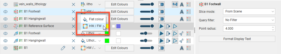
You can change the way the different objects that make up the vein are displayed using options in the shape list:
Refining Veins
To edit a vein’s settings, double-click on it in the project tree. In the Lithologies tab, change the lithologies assigned to each side of the surface, if required. For information on the settings in the Surfacing and Inputs tabs, see Surfacing Options for Veins below.
Surfacing Options for Veins
Surfacing options for veins can be changed by double-clicking on the surface in the project tree and then clicking on the Surfacing tab. There are additional settings related to boundary filtering and snapping to data in the Inputs tab.
Boundary Filtering
When data objects are added to a surface, there are two ways to handle the data that lies outside the surface’s boundary:
- Filter the data. The surface is only influenced by the data that falls inside the surface’s boundary.
- Leave the data unfiltered. The surface is influenced by the data both inside and outside the surface’s boundary.
The boundary of a vein can be the geological model boundary or a fault block boundary.
The Boundary filter setting determines how data used to define the surface is filtered:
- Off. Data is not filtered.
- All data. All data is filtered.
- Drilling only. Only drillhole data and data objects derived from drillhole data are filtered.
- Custom. Only the data objects specified in the Inputs tab are filtered.
The Filter segments by boundary setting in the Inputs tab is enabled by default when the Boundary filter setting in the Surfacing tab is All data or Drilling only. When Filter segments by boundary is enabled, the vein surface will only be influenced by the segments that falls inside the vein boundary.
Snapping to Data
Often, surfaces should honour drillhole data and treat data objects such as polylines and GIS data as interpretations, as discussed in Honouring Surface Contacts.
There is a Snap to data setting for a geological model as a whole that is set in the Geological Model > General tab (see Editing a Geological Model). Snap to data can also be set on a surface-by-surface basis by double-clicking on the surface in the project tree and then clicking on the Surfacing tab.
For individual contact surfaces, the options are:
- Inherit from GM. The setting for the geological model as a whole is used. This is the default setting.
- Off. Surfaces do not snap to the data used to create them.
- All data. Surfaces snap to all data within the Maximum snap distance, which includes drillhole data and any data added to the surfaces.
- Drilling only. Surfaces snap to drillhole data and data objects derived from drillhole data within the Maximum snap distance but not to other data used to modify the surfaces.
- Custom. Surfaces snap to the data objects indicated in the Inputs tab for each surface.
Take care in enabling snapping and in selecting what data the surface will snap to, as the more data you include, e.g. by setting a large Maximum snap distance or selecting All data for Snap to data, the greater the possibility that errors in the data or assumptions inherent in interpretations (e.g. polylines) will cause distortions in the meshes. If you do enable snapping, it is best to snap only to drilling data. See Honouring Surface Contacts for more information on these settings.
If you need a surface to honour drillhole data but treat other data objects as interpretations, select Drilling only. To honour some data objects while treating others as interpretations, select Custom, then click on the Inputs tab to enable snapping for individual objects.
Surface Resolution
Note that although you can change the Surface resolution for a vein, the Adaptive option is not available, even when the resolution for the geological model is set to be Adaptive.
Vein Thickness
Veins have two thickness settings that force the vein to maintain a minimum or maximum thickness. If footwall and hangingwall points are in pairs, it is not usually necessary to set the Minimum thickness or Maximum thickness.
- If the vein intersects itself, set the Minimum thickness to a value that is less than the minimum distance between any two contact points.
- If the vein widens out toward the edges of the geological model set the Maximum thickness to a value that limits the effects of long segments.
If the Pinch out option is enabled, you will not be able to set the Minimum thickness.
If you set the Maximum thickness and Pinch out, the Pinch out is applied before the Maximum thickness.
Note that if Snap to data is enabled, snapping occurs after the vein thickness has been calculated. If it appears that the vein surface is not honouring the thickness setting, check what data the surface is snapping to.
Vein Pinch Out
Vein walls can be set to pinch out where drillhole data indicates they do not occur. This is achieved by creating ‘outside’ intervals on drillholes that do not have an interior vein segment. These intervals are then flipped with respect to interior vein intervals, which, in effect means the footwall and hangingwall orientation has the opposite sense to the nearest interior intervals. This forces the hangingwall and footwall surfaces to cross, thereby pinching out.
The Pinch out option is disabled when a vein is first created. To enable it, double-click on the vein in the project tree and click on the Surfacing tab. Tick the box for Pinch out. Click OK to process the changes. The vein will be updated and pinch out points (![]() ) will be added to the vein in the project tree.
) will be added to the vein in the project tree.
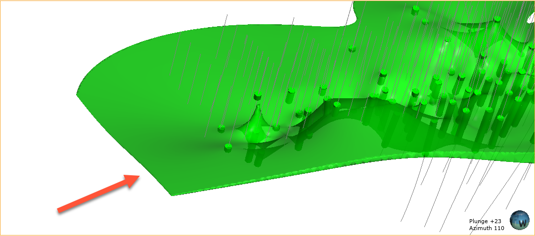
For this vein, the surface occurs even where the vein lithology (green cylinders) does not occur and terminates at the boundary of the geological model:
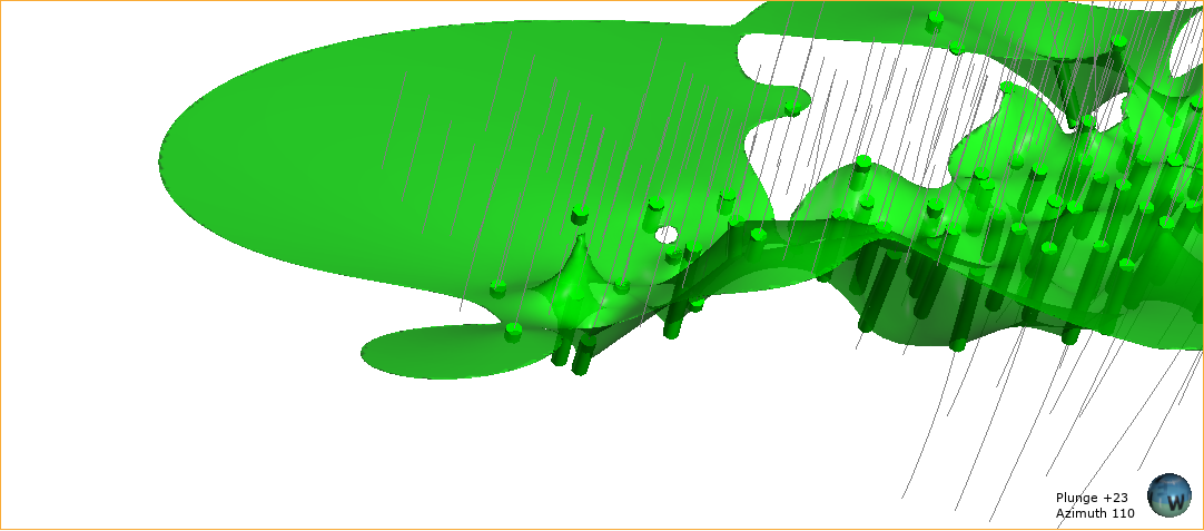
When the vein is set to pinch out, it tapers out where the vein lithology does not occur:
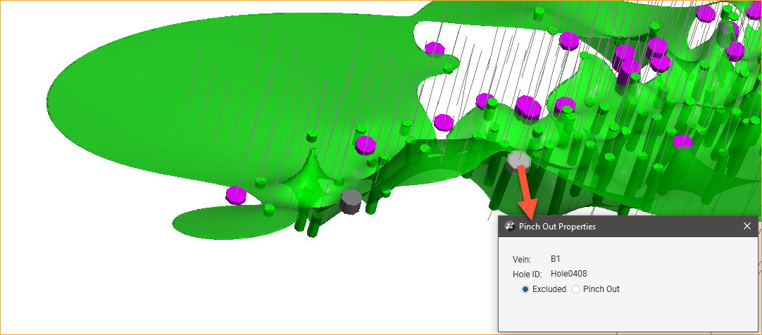
You can change how much the vein pinches out by excluding some pinch out segments. To do this, right-click on the pinch out segments (![]() ) in the project tree and select Edit in Scene. The Pinch Out Properties window will appear in the scene. Click on a segment to view information about it and set it to be Excluded, if required. Note that the segments displayed in the scene below are the pinch out segments rather than the drillhole segments shown in earlier scenes. The grey segments are excluded and the currently selected segment is highlighted in the scene:
) in the project tree and select Edit in Scene. The Pinch Out Properties window will appear in the scene. Click on a segment to view information about it and set it to be Excluded, if required. Note that the segments displayed in the scene below are the pinch out segments rather than the drillhole segments shown in earlier scenes. The grey segments are excluded and the currently selected segment is highlighted in the scene:
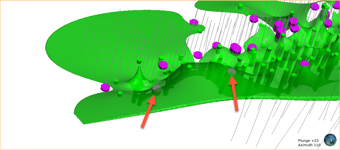
Click the Save button (![]() ) to view the effect of the excluded pinch out segments on the vein. Excluding the two segments results in the vein terminating at the boundary of the geological model:
) to view the effect of the excluded pinch out segments on the vein. Excluding the two segments results in the vein terminating at the boundary of the geological model:
The Vein Reference Surface
A vein includes a reference surface (![]() ) that is the best fit for the objects that make up the hangingwall and footwall surfaces.
) that is the best fit for the objects that make up the hangingwall and footwall surfaces.
A vein can have a curved reference surface, a planar reference surface or it can use another mesh in the project. Double-click on the reference surface in the project tree; this opens the Edit Vein Reference Surface window and you can see what option is being used for the surface. In this example, the B1 vein has been created from lithology data and so it has a curved reference surface and the midpoints for the vein lithology are used as Input values:

Each option is described below:
Curved Reference Surface
The Curved reference surface option is the default for veins created from lithology data and the objects used to build the reference surface are shown in the Input values part of the Edit Vein Reference Surface window:
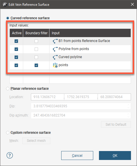
You can enable or disable the different data objects to see their effects on the vein by ticking and unticking the Active box, then clicking OK to reprocess the vein.
The Boundary filter setting for each object determines whether or not the data that lies outside the reference surface’s boundary is filtered.
- Tick Boundary filter so that the surface is only influenced by the data that falls inside the reference surface’s boundary.
- Untick Boundary filter if you want the surface to be influenced by the data both inside and outside the reference surface’s boundary.
Boundary filtering for the midpoints used to create a curved reference is controlled by the setting for the vein itself. See Boundary Filtering in Surfacing Options for Veins for more information.
The Curved reference surface option is the default for veins created from lithology data, whereas the Planar reference surface option is the default for veins created from other types of data. In order for a vein created from data other than lithology data to use a curved reference surface, other data must be added to it. To add data, right-click on the reference surface in the project tree and select Add or Edit.
Using the Add option, you can add points data, GIS data or polylines to the surface. Using the Edit option, you can add a polyline to the reference surface, but its editing options are limited in that you can not add tangents or normals to the polyline.
Planar Reference Surface
Veins created from objects other than lithology data use a planar reference surface by default. To edit a planar reference surface, double-click on the reference surface in the project tree. This will open the Edit Vein Reference Surface window and display controls in the scene for adjusting the plane.
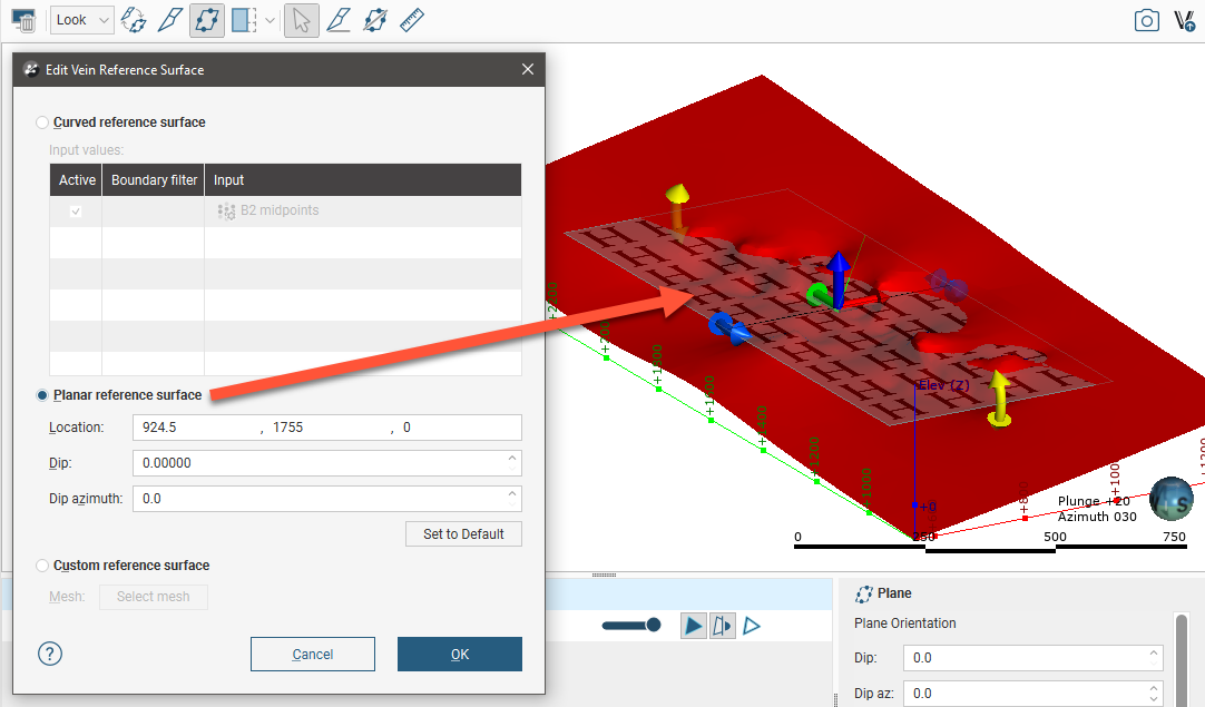
These handles work in the same manner as the moving plane controls, as described in The Moving Plane.
To use a planar reference surface for a vein created from lithology data, double-click on the reference surface to open the Edit Vein Reference Surface window, then select the Planar reference surface option. Adjust the plane in the scene, then click OK to reprocess the vein.
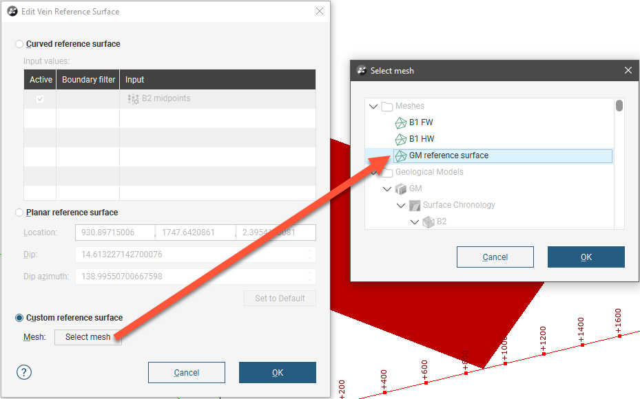
Custom Reference Surface
If you wish to use another surface in the project as a reference surface, double-click on the reference surface to open the Edit Vein Reference Surface window. Enable the Custom reference surface option, then select the mesh from those available in the project:
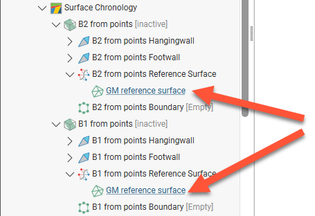
This option is useful if you wish to use a mesh in the project as, for example, a common reference surface for all veins in a geological model. To do this, edit the reference surface for each vein so they all use the common surface for the Custom reference surface option:
The Vein Boundary
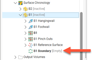
When a vein is first created, its boundary (![]() ) is empty:
) is empty:
Once a vein has been created, you can change its boundary by adding a polyline an adjusting the boundary plane.
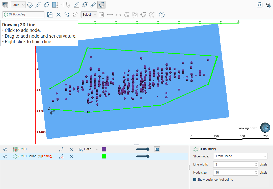
To edit the boundary using a polyline, right-click on it in the project tree and select Edit. The current vein boundary will appear in the scene, together with drawing controls. Begin drawing the new boundary, as described in Drawing in the Scene, ensuring that the polyline drawn closes and does not intersect itself.
When you save the boundary, the vein will be updated to reflect the changes made. If you want to revert to the original boundary, right-click on the boundary object (![]() ) and select Delete Polyline.
) and select Delete Polyline.
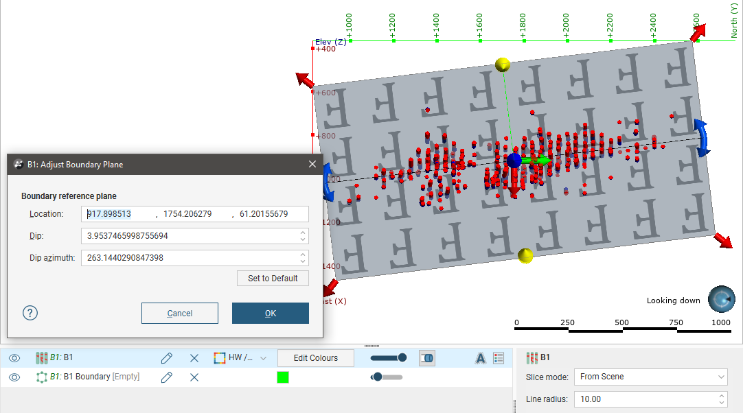
The other option is to adjust the boundary plane. To do this, right-click on the boundary in the project tree and select Adjust Plane. The plane will be displayed in the scene, along with the Adjust Boundary Plane window. You can use the handles on the plane to adjust its position or you can enter the information in the Adjust Boundary Plane window.
Click OK to apply the changes to the vein.
To revert to the original boundary plane, right-click on the boundary object and select Adjust Plane. In the Adjust Boundary Plane window, click on the Set to Default button and click OK.
Editing Vein Segments
When a vein has been created from contact points, you can change the vein segment settings by double-clicking on the vein segments object (![]() ) in the project tree. This opens the Edit Vein window:
) in the project tree. This opens the Edit Vein window:
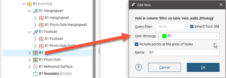
When extracting the hangingwall and footwall points, Leapfrog Geo automatically includes points at the ends of the drillholes. To exclude these points, untick the Include points at the ends of holes option in the Edit Vein window.
If you need to change the orientation of individual vein segments, e.g. for curved veins, you can do this by right-clicking on the vein segments object (![]() ) in the project tree and selecting Edit In Scene. If the vein segments object is already in the scene, you can edit it by clicking the Edit button (
) in the project tree and selecting Edit In Scene. If the vein segments object is already in the scene, you can edit it by clicking the Edit button (![]() ) in the shape list.
) in the shape list.
The Vein Segment Orientations window will appear in the scene. Click on a vein segment to view information about that segment:
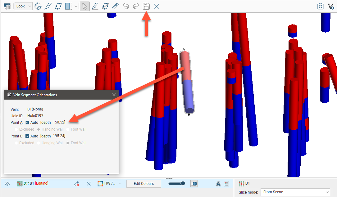
Points A and B are labelled in the scene and can be changed by unticking the box for each point and choosing whether to exclude the point or make it a hangingwall or footwall point. Once you have finished editing vein segments, click the Save button (![]() ).
).
If you wish to return to the default settings, ensure the Auto box is ticked for each point.
Got a question? Visit the Seequent forums or Seequent support