Boundaries in Leapfrog Works Projects
This topic discusses boundaries in Leapfrog Works. It is divided into:
A newly-created project has only a basic set of X-Y-Z coordinates, and the coordinate system used by the project is determined by the data imported to the project. It is not necessary to specify what coordinate system is used; however, it is necessary to ensure that data you import into the project uses the same coordinate system.
Often the best way to set the coordinates for the project as a whole is to import a map or aerial photo. Adding georeference data to a map will set the location of the map in three-dimensional space and set the coordinates for the project. See Importing a Map or Image for more information.
An important consideration in defining the project space is setting the clipping boundary. See The Clipping Boundary.
It is not necessary to define a topography to model in Leapfrog Works, but a defined topography can be used as an upper boundary for all models built in the project. See Defining a Topography.
Part of creating many objects in Leapfrog Works is defining the basic rectangular boundary that defines the object’s extents. See Object Extents.
You can modify the extents of geological models and interpolants using surfaces created from different types of data. See Modifying a Geological Model’s Boundary and Modifying an RBF Interpolant’s Boundary With Lateral Extents.
The Clipping Boundary
An important consideration in defining the project space is setting the clipping boundary.
The default clipping boundary in a new project file encompasses everything in the project and grows as more data is added to the project. It is not necessary to set the clipping boundary. However, the clipping boundary defines the limits of the X-Y coordinates for the region in which data will be imported and models built and so defines the region in which calculations are made. Restricting the size of the clipping boundary limits the area in which calculations are made and is especially important if you are working with a large dataset.
The best way to set the clipping boundary is using an imported map or aerial photo, as this provides a visual reference that is helpful in working with data added to the project in the future. GIS data or borehole data can also be used to set the clipping boundary.
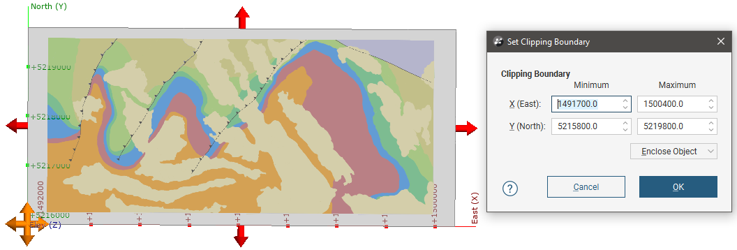
To set the clipping boundary, add to the scene the objects you wish to reference in setting the boundary. Right-click on the Topographies folder or on the GIS Data, Maps and Photos folder and select Set Clipping Boundary. The Set Clipping Boundary window will be displayed, together with controls in the scene you can use to resize the clipping boundary:
There are three ways to define the rectangular clipping boundary:
- Enter the coordinates.
- Select Enclose Object and choose from the list of objects in the project. The clipping boundary will be updated using the selected object.
- Use the controls that appear in the scene. The orange handle adjusts the corner of the clipping boundary and the red handles adjusts its size.
When you have finished adjusting the clipping boundary, click OK.
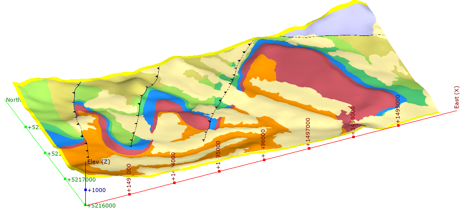
If you are going to import elevation data and use it to create a topography, it is important to set the clipping boundary before creating the topography. For example, here a map has been imported and a topography (yellow) has been created from an elevation grid. The map is displayed draped on the topography:
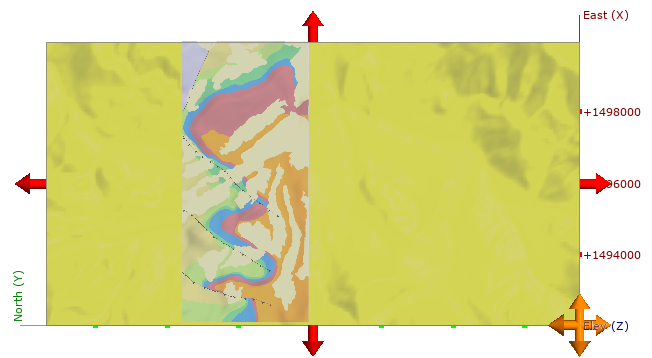
The red arrows and orange handle show the clipping boundary, which has been allowed to expand to encompass all data imported to the project. Because the topography was created before the clipping boundary was set, all the data in the imported elevation grid has been used and the resulting topography is larger than might be practical. Clearly, if the intention is to model within the area on the map, the clipping boundary should be limited to the region indicated by the map.
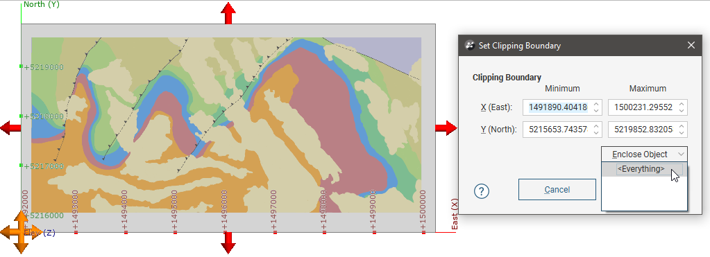
If the map is the only object in the project, it can easily be used to set the clipping boundary by selecting <Everything> from the Enclose Object list:
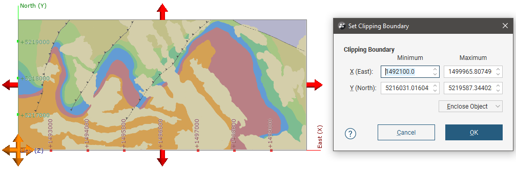
This results in a clipping boundary that is limited to the extents of the map:
Once the clipping boundary has been set, further data imported into the project will be clipped to it. For example, importing an elevation grid and using it to create a topography only after the clipping boundary has been set to the map extents will result in a topography (with the map draped) that looks like this, with only a narrow yellow boundary:
Object Extents
Part of creating many objects in Leapfrog Works is defining the basic rectangular boundary that defines the object’s extents. There are generally two options for defining an object’s extents:
- The first option is to define extents that are independent of other objects in the project. You can do this by entering coordinates or adjusting controls in the scene to set the size and shape of the extents. The new object’s extents are fixed to the specified size. This is a good choice if, for example, you are building a geological model from a map and wish to define the model extents based on information on the map.
- The second option is to define extents based on other objects in the project. This is done by selecting the other object from the Enclose Object list that appears in many Leapfrog Works screens.
For both methods, the new object’s extents are fixed to the selected size. Using the Enclose Object list does not link the two objects; it is simply using the X-Y-Z coordinates of the original object as the basis for the new extents.
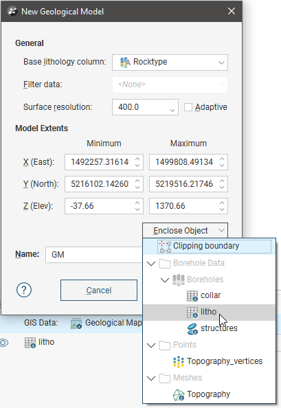
For example, here, a geological model’s extents could be defined using the lithology segments used as the base lithology:
When creating some objects, you have the option of sharing extents with another object. This is the case with editable meshes (![]() ), where you can choose whether the mesh has its own extents or shares extents with other objects in the project. Shared extents are updated when the original object’s extents are updated.
), where you can choose whether the mesh has its own extents or shares extents with other objects in the project. Shared extents are updated when the original object’s extents are updated.
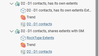
If you are unsure about relationships between objects, expand them in the project tree to view more information. Here, two meshes have been defined from the same set of points. The first mesh has its own extents that are not updated by other objects in the project, whereas the second mesh shares its extents with those of the RockType geological model.
Geological models and interpolants are created with a basic set of rectangular extents that can then be refined by adding extents created from other data in the project. Creating extents is a useful way of restricting modelling to a particular area of interest. For example, modelling can be restricted to a known distance from borehole data by applying a distance function as a lateral extent. See Modifying a Geological Model’s Boundary for more information.
Extending a Surface
Geological models created in a Leapfrog Works project automatically use the defined topography as an upper boundary. If a model is defined that extends outside the topography, an error will occur. A similar error occurs when surfaces used in geological models do not extend outside the model’s extents. In all cases, Leapfrog Works cannot process the surface and an error will be displayed.
In this example, an error has occurred during the process of creating a geological model because the model extents (pink) do not fall completely inside of the topography:
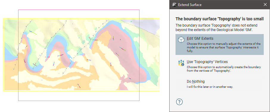
In order for Leapfrog Works to be able to divide the model into separate volumes, the topography needs to be extended to enclose the model’s boundary or the model’s boundary needs to be restricted so it falls inside the topography.
The solutions proposed will depend upon the data used to create the surfaces that conflict, but fall into three broad categories:
- Reduce the size of the model’s or interpolant’s extents. Click the Edit Extents button. This will open the object’s Boundary window and you can change the boundary.
- Enlarge the topography by manually adjusting it. Click on the Edit Topography Extents button. This option is only available when the topography has been created from more than one data source. See Adding Height Data to the Topography and Changing Topography Settings.
- Use the surface’s vertices to create the boundary or contact with extents large enough to be used in the model or interpolant. Click the Use Vertices button to create a new vertices object and use it as the source data for the boundary or contact.
If you have a solution to the problem that is not covered by the options presented, click Do Nothing. For example:
- If the topography is not large enough, there may be additional data available. If it is not already in the project, import the data and add it to the topography as described in Adding Height Data to the Topography.
- If a surface being used to define a contact surface or boundary in a geological model or interpolant is not large enough, you can add additional data to the surface.
Using vertices to create the boundary or contact results in the creation of a new points object that will be saved in the Points folder. For example, here the geological model uses vertices to create the “Topography” used as an extent:
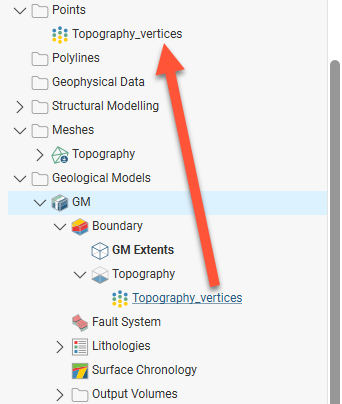
Using topography vertices can take some time to process.
An additional disadvantage to using vertices is that the vertices object created is not linked to the original object, and when the object used to create the vertices changes, the vertices will not be updated.
Got a question? Visit the Seequent forums or Seequent support