Defining a Topography
It is not necessary to define a topography to model in Leapfrog Works, but a defined topography can be used as an upper boundary for all models built in the project.
A key advantage of defining a topography is that it provides consistent elevation data for objects imported to and created in the project. The quality of elevation information can be poor compared to X- and Y-coordinates, which can create problems when using objects to build a model. A topography can be created from the most reliable elevation data, and other objects can have elevation set from this topography.
An important consideration when defining the topography is ensuring that it is large enough to encompass the models you will be building in the project. If you create a small topography but then later create a model that extends outside the topography, you will need to enlarge the topography, which can result in considerable reprocessing of all objects in the project that use the topography as a boundary. See Extending a Surface for more information.
This topic describes creating and working with a topography. It is divided into:
- Topography From Elevation Grid
- Topography From Surfaces, Points or GIS Vector Data
- Fixed Elevation Topography
- Adding Height Data to the Topography
- Changing Topography Settings
- Topography Display Options
- Setting Elevation for Collar Points
The topography can be created from an imported elevation grid, points data, surfaces and GIS data. It is not necessary to decide on a single source of information, as information can be combined, and you can add and remove data as required.
Once defined, you can export the topography as a mesh or as an elevation grid. See:
Topography From Elevation Grid
There are two ways to create the topography from an elevation grid:
- Right-click on the Topographies folder and select New Topography > Import Elevation Grid. Import the grid as described in Importing an Elevation Grid.
- Import the grid using the Meshes folder and then right-click on the Topographies folder and select New Topography > From Surface.
Enter a name for the topography and click OK. A hyperlink to the elevation grid will appear in the Topographies folder under the defined topography.
Once the topography has been defined, additional height data can be added by right-clicking on the topography and selecting from the options available. See Adding Height Data to the Topography for more information.
Topography From Surfaces, Points or GIS Vector Data
To create the topography from a surface, points or GIS data, first import the data into the project.
- Import surfaces into the Meshes folder.
- Import borehole data into the project or points data into the Points folder.
- Import GIS vector data into the GIS Data, Maps and Photos folder.
Next, right-click on the Topographies folder and select one of the New Topography options. A list of suitable objects available in the project will be displayed. Select the required object and click OK. Enter a name for the topography and click OK. A hyperlink to the source object will appear in the Topographies folder under the defined topography.
Once the topography has been defined, additional height data can be added by right-clicking on the topography and selecting from the options available. See Adding Height Data to the Topography for more information.
See also Changing Topography Settings below.
Fixed Elevation Topography
If you don’t have any data suitable for creating a topography, you can set a fixed elevation. To do this, right-click on the Topographies folder and select New Topography > Fixed Elevation. In the window that appears, enter a value for the elevation and click OK. Enter a name for the new topography and click OK.
The new topography will appear in the project tree under the Topographies folder.
Once a topography has been defined, the only way to set a fixed elevation is to remove the objects that have been used to define the topography. To do this, right-click on the hyperlinked object and click Remove. You will then be able to set a fixed elevation for the topography.
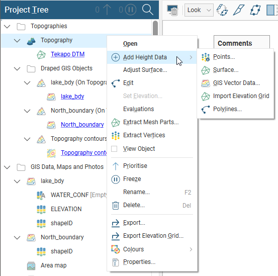
Adding Height Data to the Topography
When creating the topography, it is not necessary to decide on a single source of information, as information can be combined. Once the topography has been defined, additional height data can be added by right-clicking on the topography and selecting from the options available:
It is not possible to add structural data or polylines with orientation information to the topography. If you edit the topography with a polyline, your options for editing the polyline will be limited.
For points, surfaces and GIS vector data, you will be prompted to select from the data sources available in the project. For an elevation grid, see Importing an Elevation Grid.
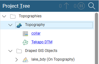
All data objects used to define the topography will appear under the topography, hyperlinked to their parent objects:
When you have added data to the topography, you may need to enlarge the topography extents. See Changing Topography Settings below.
To remove data objects from the topography, either:
- Delete the object from the topography. To do this, right-click on the hyperlinked object and click Remove.
- Delete the object from the project. If you choose this option, consider carefully the effects on other objects in the project, as once an object is deleted, it cannot be recovered.
When the topography is defined from multiple objects, you can set the resolution of the topography by double-clicking on it. See Changing Topography Settings below.
Changing Topography Settings
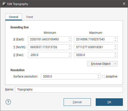
When the topography is created from points or GIS data or when the topography is created by combining data, you can change its boundary and resolution and apply a trend. To do this, double-click on the topography in the project tree. The Edit Topography window will appear:
Changing the Size of the Topography
In the General tab, you can change the topography extents. Use the controls in the scene or enter the required values in the Bounding Box fields.
Topography Resolution
The resolution of the topography depends on how it was created.
- When the topography is created from a single mesh, the resolution of the topography is set from the resolution of the mesh and can only be changed when the mesh is imported. If you wish to change the resolution of the topography, you must first add more height data to the topography. See Adding Height Data to the Topography.
- When the topography is created by setting a fixed elevation, the resolution cannot be set.
When the topography is created from points or GIS data or when the topography is created from combining data, you can set its resolution in the Edit Topography window.
When you set a specific Surface resolution without enabling the Adaptive option, the triangles used will be the same size for the whole topography. When you enable the Adaptive option, the resolution of the topography will be affected by the availability and density of real data. See Surface Resolution in Leapfrog Works for more information on these settings.
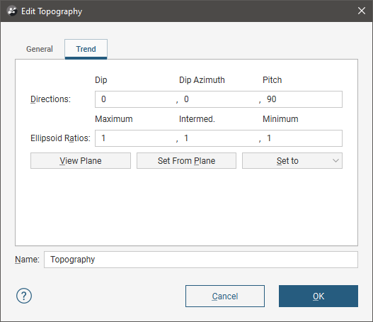
Applying a Trend to the Topography
In the Trend tab, you can apply a trend to the topography:
See Global Trends for more information.
Topography Display Options
To display the topography in the scene window, either:
- Right-click on the topography in the project tree and select View Object.
- Click on the topography object and drag it into the scene.
The topography will be displayed in the scene window and in the shape list:
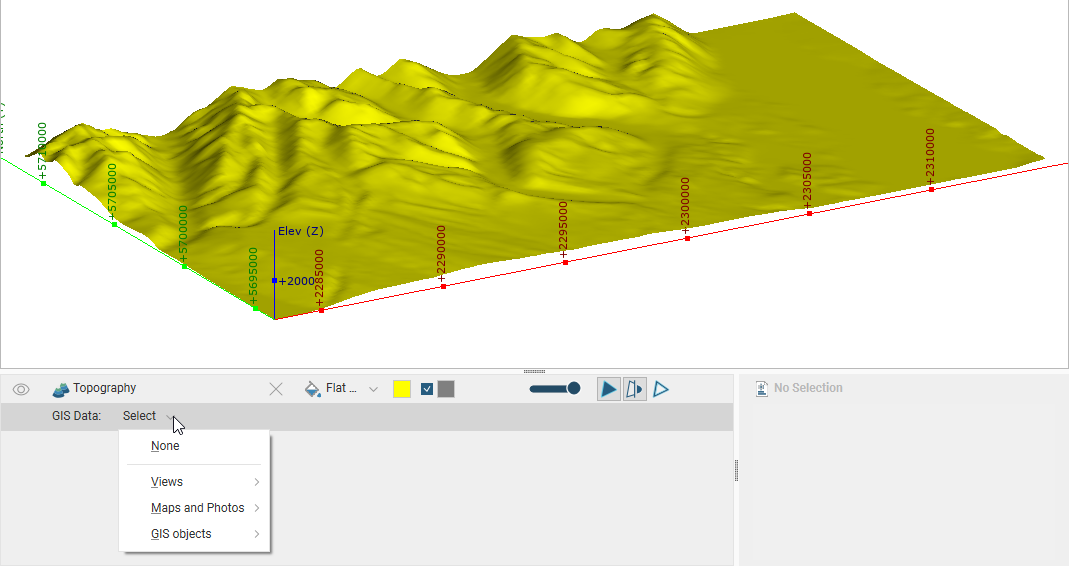
The topography object in the shape list provides additional controls that can be used to change the way the topography is displayed and highlight features of interest. For example, selecting an imported map from the list results in it being displayed draped onto the topography:
The list is organised into:
- Views. This contains options for creating and editing custom topography views and also lists any views already defined. With custom topography views, you can view multiple GIS objects, maps and contours. See Custom Topography Views for more information.
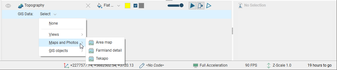
- Maps and Photos. This lists all images stored in the GIS Data, Maps and Photos folder.
- GIS objects. This lists all GIS data objects stored in the GIS Data, Maps and Photos folder.
Setting Elevation for Collar Points
You can set the elevation for all collar points or for a subset of collar points by projecting them onto a surface. This overwrites elevation values in the z column of the collar table, using the data from the selected surface. If the surface does not intersect vertically with the selected points, you can choose how the z values for those unprojected points will be handled.
To set the elevation for collar points from a surface, right-click on the collar table in the project tree and select Set Elevation. The Set Elevation from Surface window will appear:
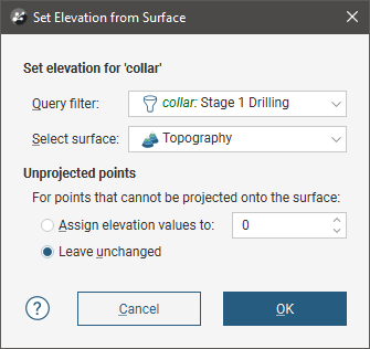
Select from the surfaces available in the project and set a query filter, if required.
Next, select how unprojected points should be handled. There are three options:
- Assign elevation values to sets the z values to a fixed elevation for all unprojected points.
- Leave elevation values empty clears the z values for all unprojected points.
- Leave unchanged makes no changes to the z values for unprojected points.
Click OK to set elevation values.
The collar table will be updated with an additional column, z_on_terrain:
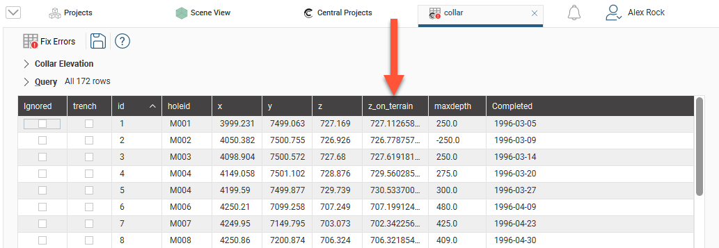
The original z values are preserved in the z column. To switch back to the original z values, click on Collar Elevation, then select the original column:
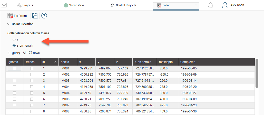
If you switch back to using the original z column, the z_on_terrain column will remain in the collar table.
Got a question? Visit the Seequent forums or Seequent support