Geological Models
The model building process involves several key steps:
- Creating the project and setting up the modelling environment
- Importing drillhole data and correcting errors
- Importing other required data
- Visualising the data in the scene and inspecting it to make sense of the model that will be built. It is at this stage that you might create new drillhole data columns to select data that will be the basis of geological models.
- Creating a basic GM, then refining its boundary and defining a fault system
- Modelling the contact surfaces
- Setting the cutting relationships between the different contact surfaces and generating volumes
A fault system can also be defined that divides the geological model into subunits in which the internal structure can be defined independent of the other subunits in the model. This is described in Faulted Models.
The rest of this topic describes the process of creating a geological model. It is divided into:
- Creating a New Geological Model
- The Geological Model in the Project Tree
- Geological Model Display
- Copying a Geological Model
- Creating a Static Copy of a Geological Model
- Geological Model Volumes and Surfaces Export Options
- Extracting Model Volumes
A geological model can be created using only a basic set of parameters. The only parameter that cannot be changed once the model has been created is the base lithology.
Creating a New Geological Model
To create a new geological model, right-click on the Geological Models folder and select New Geological Model. The New Geological Model window will open, together with a set of controls in the scene that help in defining the model extents.
The Base Lithology
Select the drillhole data column that will be used as the basis of a model from the Base Lithology Column list. If you do not wish to use lithology data as the basis for the model, select <None>. This may be the case if, for example, you want to build a model from points data or from an imported map. If you select <None>, you will need to manually define the lithologies that will be modelled.
If more than one column of lithology data is available for creating models, be sure to choose the correct one as it cannot be changed once the initial model has been created. If after creating and modifying the model, you find you need to modify the drillhole data, resulting in a new lithology column, you can use that new column to create contact surfaces using Other Contacts options.
You can also filter the drillhole data used to build the geological model using query filters. To do so, select the required query filter from the Filter data list. Once the model has been created, you can remove the filter or select a different filter.
Surface Resolution
The surface resolution setting Leapfrog Geo automatically uses as the default is based on the data available in the project. Set the surface resolution for the model as a whole and choose whether or not the resolution will be adaptive. See Surface Resolution in Leapfrog Geo for more information on the effects of these settings.
Later, while refining the model, you can change the resolution of each surface and enable or disable adaptive resolution. See Surface Resolution for a Geological Model.
Model Extents
A geological model is initially created with a basic rectangular set of extents aligned with the south/north and east/west axes. You can define the model’s extents in three ways:
- Enter the coordinates.
- Select Enclose Object and choose from the list of objects in the project. If the model is based on drillhole data, select the lithology segments from the Enclose Object list.
- Use the controls that appear in the scene. The orange handle adjusts the centre of the plane and the red handles adjust the size.
See Object Extents for more information.
Enter a Name for the model that describes the purpose of the model. This Name will be used in naming the objects that will be added to the model. Click OK to create the new model. The new geological model will be created and added to the Geological Models folder.
See Editing a Geological Model for information on how to change the basic settings for the model.
The Geological Model in the Project Tree
The objects under the geological model in the project tree represent different parts of the model:
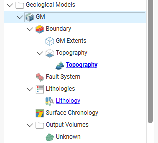
- The Boundary object defines the limits of the geological model. When the model is first created, this is the rectangular model extents. If a topography has been defined, it is automatically used for as the upper boundary. See Modifying a Geological Model’s Boundary for more information about modifying the boundary.
- The Fault System object defines faults and their interactions in the model. See Faulted Models.
- The Lithologies object describes all the lithological units to be modelled and the colours that are used to display them on the screen. It is generated automatically from all the lithologies identified in drillhole data selected when the model is created. If no column was selected, you will need to define the lithologies manually before you start modelling the lithology layers.
- The Surface Chronology object describes the contact surfaces in the model, organised in chronological order, from youngest to oldest. These surfaces and their chronology determine how the volume inside the model extents is divided into lithological units. When the model is first created, the Surface Chronology is empty, but it will eventually hold all contact surfaces and inputs to them.
- The Output Volumes folder contains all the volumes generated in building the geological model. When the model is first created, the Surface Chronology is empty and so there is only a single output volume in the Output Volumes folder. This volume fills the model’s extents and is called “Unknown”. Once contact surfaces have been generated and added to the Surface Chronology object, new volumes will be generated and added to the Output Volumes folder.
Geological Model Display
Right-click on the geological model in the project tree to view its display options:
- The View Object option adds the geological model to the shape list as a single object. You can also display the geological model in this way by dragging it from the project tree into the scene. Change the visibility of the model’s volumes by clicking the Edit Colours button in the shape list.
- The View Output Volumes option adds the model to the scene as a series of output volumes. It is the equivalent of dragging the Output Volumes folder into the scene. Change the visibility of the model’s volumes individually.
- The View Surface Chronology option displays the surfaces that are used to divided up the model.
- The View Fault Block Boundaries option is only available when a fault system has been defined and enabled for the model. Selecting View Fault Block Boundaries displays the fault blocks without displaying the lithology layers.
Copying a Geological Model
Creating a copy of a geological model is a useful way of experimenting with changes to a model.
To copy a geological model, right-click on it in the project tree and select Copy. Enter a name for the copy of the model and click OK. The copy will be added to the project tree.
Creating a Static Copy of a Geological Model
Creating a static copy preserves a snapshot of a geological model that does not change, even when changes are made to the data on which the original model was dependent. This is a useful way of storing historical models and comparing models. Static copies can be exported from Leapfrog Geo, as described in Geological Model Volumes and Surfaces Export Options below.
To create a static copy of a geological model, right-click on it in the project tree and select Static Copy. Enter a name for the copy of the model and click OK. The copy will be added to the Geological Models folder.
You can also import static geological models from Central, as described in Importing Central Data Objects.
In the project tree, the static copy (![]() ) is made up of a Legend object (
) is made up of a Legend object (![]() ), a boundary (
), a boundary (![]() ), a fault system (
), a fault system (![]() ), the output volumes (
), the output volumes (![]() ) and all surfaces created in building the model. The surfaces can be used elsewhere in the project and exported for use in other projects.
) and all surfaces created in building the model. The surfaces can be used elsewhere in the project and exported for use in other projects.
Static models created in versions of Leapfrog Geo before 2.2 copied only the output volumes and the legend, and the static model appeared in the shape list only as a single line. When these static models are upgraded and displayed in the scene, the individual output volumes will be added to the shape list.
To view the date a static copy was created, right-click on it in the project tree and select Properties. The date the copy was created is shown in the General tab.
Geological Model Volumes and Surfaces Export Options
There are three options for exporting a geological model’s output volumes and surfaces. These are:
- Export an output volume or a surface as a mesh. Right-click on it in the project tree and click Export. You will be prompted for a file name and location. See Exporting a Single Mesh.
- Export an output volume as a thickness grid. Right-click on it in the project tree and click Export Thickness Grid. See Thickness Grids.
- Export multiple output volumes and surfaces. Right-click on the geological model in the project tree and select Export. See Exporting Multiple Meshes from Models.
When exporting output volumes, the Merge output lithology volumes setting in the geological model’s General tab (see Editing a Geological Model) determines how the output volumes are handled when they are exported. If this setting is enabled, internal walls and surface seams will be removed from volumes of the same lithology.
Extracting Model Volumes
There are number of options for extracting meshes from geological model output volumes. These options are available by right-clicking on volumes in the Output Volumes folder and selecting Extract Mesh. There are five options:
- Mesh Parts
- Component Surfaces
- Younger Surfaces
- Older Surfaces
- Boundary Surfaces
The Mesh Parts option is the same as the option available on meshes elsewhere in the project. See Extracting Mesh Parts.
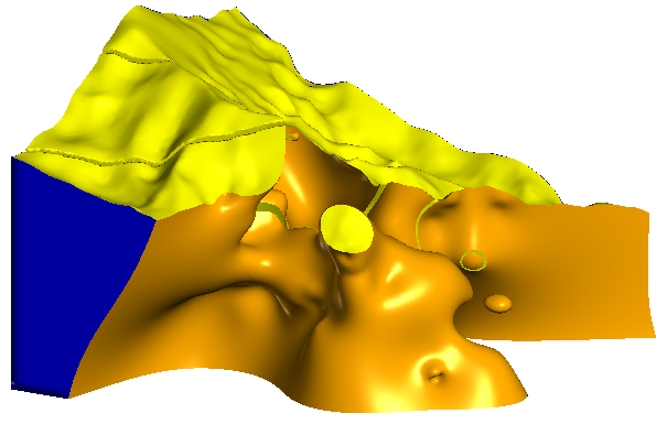
The Younger Surfaces, Older Surfaces and Boundary Surfaces options extract different parts of the selected volume, which are saved into the Meshes folder. Here, the boundary surfaces are shown in blue, the younger surfaces in yellow and the older surfaces in orange:
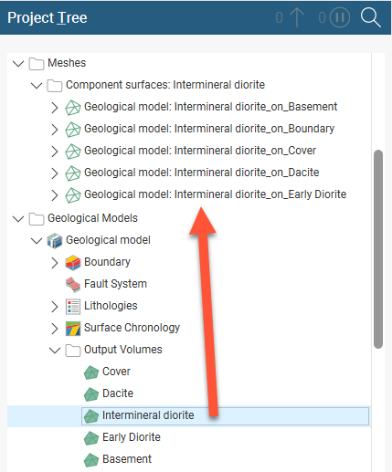
Component Surfaces extracts a separate surface for each volume the selected volume interacts with, including the boundary. The component surfaces are named after the boundary they are derived from and saved into a subfolder in the Meshes folder. For example, here meshes have been extracted for each contact with the Intermineral diorite volume:
Got a question? Visit the Seequent forums or Seequent support